Disc screen fundamentals: troubleshooting, tips, and best practices
A comprehensive guide to the efficient operation and maintenance of disc screens for screening woody biomass

What are disc screens used for?
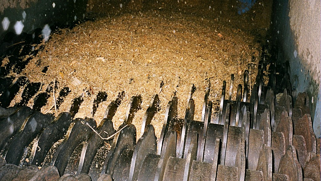
The disc screen is a simple piece of equipment that is ideal for screening woody biomass. It consists of a series of driven shaft assemblies mounted in a frame. Each rotor shaft assembly has profiled discs mounted at regular spacings. The discs from one shaft interleaf with those on the adjacent shafts, creating open areas between the discs and the shafts.
How disc screens work
Incoming material is fed onto one end of the screen. The shaft assemblies rotate, and the discs agitate the material and move it along the screen. Pieces of material that are smaller than the spacing between the discs and shaft assemblies fall through the screen. The pieces that are larger than the openings are then conveyed along the top of the discs and pass over the end of the screen.
Disc screens are particularly useful for screening biomass for the following reasons:
- They provide good agitation, which is necessary for separating the biomass particles that tend to knit together
- They are designed to handle rocks and other large, heavy contaminants without undue damage and they will withstand a lot of wear from abrasion
There are many disc screen manufacturers and many styles of screens. The purpose of this article is to provide some general design fundamentals; however, disc screen design is as much an art based on experience, as it is on science.
What factors should be considered in sizing a disc screen?
To properly size a disc screen, one must consider the volume of incoming material, the material size distribution, and the required product size.
Capacity
Disc screen capacity depends on the percentage of screen open area, which is defined as the open area divided by the total screen footprint, and is a function of the number of rotor shaft assemblies; the disc Interface Opening (IFO) and Slot Length (SL); the disc thickness; the shaft/spacer collar diameter; the screen width and length; and the rotor speed.
Shaft assemblies
The number of shaft assemblies defines the length of the screen and depends on the length of time required for all undersized material to percolate down through the material bed and pass through the screen. Disc screens should be sized such that under the maximum possible flow conditions, all the undersized material has passed through the screen with at least one to two rotors clear of the end of the screen.
Disc interface opening and slot length
Disc screen openings have two dimensions defined by the slot length and IFO. Slot length is the distance between adjacent shaft assembly spacer collars. The disc Interface Opening (IFO) is defined as the spacing between interleafed discs on adjacent shaft assemblies. If screens are fed in such a way that long pieces are not allowed to fall end-wise onto and through the screen, the maximum-sized piece passing through a screen will be narrower than the IFO and will be a little bit longer than twice the slot length plus the collar diameter.
Screens may have one or more disc IFOs. It's advisable that the first two to three rotors be sliver orientation rotors - which have a narrow IFO - with the idea being to encourage long pieces of wood to lie down on the screen and to prevent them from diving through the screen. In some screening applications, multiple size classifications may be required where fine material is removed in the first part of the screen and larger fractions in the middle and last screen sections.
The rotor discs are mounted on rotor shafts. The lowest-cost screens use discs welded directly to the shaft, but when the discs have worn out, the entire shaft assembly must be discarded and replaced. Also, care must be taken to not weaken or distort the shaft when welding.
A better rotor design utilizes discs with square holes, which are slid onto square shafts and separated by round spacer collars. A threaded locking mechanism is utilized to tighten the discs firmly on the shaft.
The periphery of the discs is profiled to provide agitation. The shape of the profile depends upon the material being handled and the vendor's specific design. Generally, six-point stars are used for wood chips, and discs with six rounded lobes are used for hog fuel and other stringy biomass. Scalping screens require discs made of abrasion-resistant steel, generally with a Bhn hardness greater than 360.
Disc thickness
Biomass scalping screen discs are generally 3/8" thick. However, most of the fines containing sand, dirt, and grit fall through the first few rotors and this part of the screen is subject to the highest wear. Therefore, it is advisable to utilize somewhat thicker discs (1/2") at the infeed part of the screen.
Rotor speed
Experience has determined a nominal rotor speed of approximately 30-50 rpm for most woody biomass depending upon disc and spacer collar outside diameters. Some applications may call for a gradually increasing speed between shafts to further separate and pull apart the interlocked material on the screen.
Generally, increasing overall screen speed will increase the amount of material rejected over the end of the screen, and will increase screen capacity. Conversely, decreasing the speed increases the dwell time and increases the amount of material passing through the screen, but decreases screen capacity.
Screen width
At a minimum, disc screens should be wider than the feed conveyor. However, the most important factor for determining screen width is the amount of material being delivered to the screen. For a given volume of material, a narrow screen will have a much deeper bed depth of material than a widescreen, and it will take much longer for the undersized material to percolate down through the bed.
Conversely, it can be difficult to spread the incoming material across the width of a wide screen. This can sometimes be done with deflector plates but on very wide screens a distribution screw or similar device might be required.
Best practices for the placement of disc screen components
Rotor shaft bearings are subject to high side loads due to material wedging between adjacent rotating discs. Therefore, one bearing on each shaft, usually the one on the drive side, should be firmly anchored against a shoulder on the shaft.
Shaft bearings should be mounted outboard of the screen frame where material cannot get into the bearing seals. The shaft assemblies should be equipped with UHMW plastic dust seals located on the outside of the frame, the intent being to minimize fugitive dusting around the shaft where it passes through the frame.
It is common to drive one rotor shaft directly from a gearbox and then drive the other shafts from the first shaft with inter-rotor drive chains. Due to the shock loads that can develop in a disc screen, it is best to limit the number of shafts driven from any one drive to eight or less. Disc screens should have slow-speed switches on the last roll in any drive sequence.
Each rotor must be driven. The usual method is to drive one rotor from the next with individual roller chain drives. Alternatively, a serpentine roller chain drive can be utilized, however, this application is limited to light-duty screens. Roller chain drives require lubrication to reduce wear and prolong life.
What causes jamming in disc screens, and how can it be addressed?
Disc screens can be jammed by wedge-shaped rocks, metal, large pieces of wood, wire, or stringy bark. Consequently, it is advisable to have an anti-jam sequence programmed into the PLC. Also, the screen drives should be interlocked to preceding conveyors such that the conveyors will stop when the screen stops.
Properly designed and constructed disc screens are rugged pieces of equipment that typically run all year without major servicing. However, the screen should be located in the system such that it can be bypassed or physically moved out of the process flow with minimal effort.
What is the best equipment configuration for handling biomass?
Generally, when handling biomass, it is best to have the screen in line with the feed conveyor, particularly where you have long pieces and big chunks of wood. Try to avoid turns of 90° onto the screen, but if necessary, provide extra height and a long, wide chute to allow the big pieces to turn without jamming.
The material should not drop directly on the top of the screen discs, as long thin pieces will dive straight through the screen.
The infeed chutework should be designed to evenly spread the material across the width of the screen. If necessary, diverters or deflectors can be added to the chutework above the screen.
The screen should have an integral infeed impact plate above the first rotor to bridge the gap between the screen end plate and the first rotor. The impact plate must be profiled with fingers that fit closely to the discs and collars of the first rotor and should be sloped, the intent being to deflect long slivers horizontally onto the screen.
Discharge chutework must be sufficiently steep so that fines will not build up in the valleys. Additionally, lining them with plastic can help to reduce build-up. Sliding surfaces should be constructed of thicker plates, preferably abrasion-resistant. The reject chutework should be strong enough to handle the impact of large pieces of wood. Large inspection /access/cleanout doors should be provided in all chutes. Plugged chute switches should be located in chutes wherever there is the possibility that chutes will plug up with material.
The screen must be high enough above the downstream equipment or bunker to discharge with suitable chute angles.
Processing dry wood and bark through disc screens can be very dusty, so the screen should be equipped with sealed covers. All system components - including conveyors, chutes, and screens - should be properly enclosed and ventilated to keep a negative pressure inside the equipment, thereby minimizing fugitive dusting.
Editor's note: This article was originally posted on November 15, 2017, and was updated on November 23, 2023.


